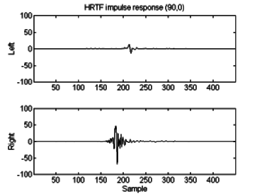
Figure 4.1: Example impulse response for 90º azimuth, 0º- elevation from SDO set.
Go back to Chapter 3, skip to Chapter 5 or return to the Index
4.0 Derivation of the HRTF
4.1 Generalization
4.2 HRTF Implementation
4.3 Headphone system response compensation
4.4 Error identification for HRTFs recorded as a pair

Figure 4.1: Example impulse response for 90º azimuth,
0º- elevation from SDO set.
While ILDs and ITDs play a dominant role in presenting azimuthal information, there are limits to the information they carry. The ILDs and ITDs for any equidistant point are equal; this is most problematic in contributing to front/back reversals. Listeners cannot distinguish between sounds in front of the head and the "mirror image" position behind the head (i.e. +30º and +150º ) without additional information.
The head-related transfer function is the source of this data. It accounts for diffraction around the head, reflections from the shoulders and most significantly, reflections from the pinnae. It is these structures of the outer ear which act as a direction-dependent filter to add elevation and front/back information to the sound signal each eardrum receives. Unfortunately, the physical composition of the pinnae varies widely across the general population. As a result of this diversity, HRTFs are also quite different for each individual.
Since the measurement of HRTFs is a time-consuming and difficult practice, it is impractical to construct a full set of them tailored to each user of an auralization system. Instead a generalized set, or possibly a choice of generic HRTFs, is implemented. There are numerous methods of arriving at these default sets. One may choose the HRTF of an individual who has demonstrated above-average localization ability, or possibly an average taken over many listeners of different background. Wightman and Kistler have performed extensive HRTF measurements and have recently proposed a set of "principal components" from which a generalized set of HRTFs may be constructed for an arbitrary source position [21]. The consensus of experiments using generalized HRTFs is an increase in front/back and up/down reversals over free-field or individualized transforms. Hence, there is a trade-off for the simplicity of using a single set of filters. Fortunately, localization ability is usually otherwise very accurate when using generalized HRTFs.
Many methods have been developed for reducing the frequency of these reversals, including the addition of head-tracking, visual stimuli, and the addition of synthetically generated reverberation; these are discussed in chapter 8.

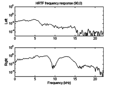
Figure 4.2: Example HRTF magnitude for 90º azimuth,
0º elevation from SDO set.
Because the HRTF represents a filter function to be applied to the source signal, a convolution is necessary. There are two methods to achieve this: first, a direct convolution may be performed with measured impulse responses (Fig. 4.1) implemented as an FIR.
Alternately, since convolution in the time domain is equivalent to multiplication in the frequency domain, an FFT may be performed, followed by multiplication by the desired filter response (Fig. 2), followed by an inverse FFT [27][28]. It is important, however, to realize the role of temporal and phase cues in the HRTF; it is not accurately represented by a magnitude (real-valued) filter [22]. The phase information must be maintained through the use of complex FFTs and a complex frequency domain filter.
The first approach, direct convolution by FIR, was the method implemented in this project. FIR coefficients may be directly retrieved from measured impulse responses utilizing either human subjects [13] or a dummy head [29]. For the purposes of this project, Wightman and Kistler's HRTFs for a representative subject (identified by her initials, "SDO") were adapted for use in the FIR stage of the auralization process.
These impulses are 512 samples in length, sampled at 16 bit, 50 kHz resolution and are available by ftp in a columnar ASCII text format [15]. In order to accommodate the limitations of the soundcard used for sample recording and playback, these HRTFs were downsampled to 44.1 kHz.
Due to this sample rate conversion, the impulse responses were reduced to 450 samples per ear. The SDO set was measured at 15º intervals in a full 360º rotation of azimuth, and in 18º intervals in a 90º angle of elevation, from 54º to -36º [13]. These 144 HRTF pairs were stored as a sequential file of raw sound samples with 450 stereo 16-bit samples apiece (SDO44.DAT). At the beginning of execution, the HRTF file was loaded into an array to allow convenient addressing of the 144 positions represented. During computation, the HRTF most nearly corresponding to the specified azimuth and elevation was used. There was no provision in this implementation for interpolation of "in-between" angles.
The SDO set of HRTFs made available by Wightman and Kistler [15] have been pre-compensated for "high-fidelity headphone response". A possible future enhancement would be the inclusion of a headphone calibration file, allowing the user to specify the make and model headphone in use. An appropriate compensation filter would be added before playback, to nullify the effect of using different headphones.
It is common practice to measure, store, and recall HRTFs as a stereo pair. They are recorded with a source displaced along a sphere centered on the middle of the head. The resulting impulses are stored as a pair referenced to the coordinates of the source relative to the center of the head. A simple example illustrates the error inherent in this method; an error which has simply been ignored in existing systems.
Let us examine the behavior of a sound source at 0º azimuth, 0º elevation (directly in front of and level with the listener). When the HRTFs are recorded at this position at a reference distance of 1 meter, it is evident that the direction vector from each ear is actually = 3.5º from center (assuming an interaural spacing of 12cm). The left ear is actually measuring the HRTF for the triplet (-3.5º , 0º , 1.002m) and the right is measuring the HRTF for (3.5º , 0º , 1.002m). While the distance variation from the 1 meter reference is negligible (one sample at 44.1 kHz is equivalent to 0.0078 meters assuming sound travels at 346 m/sec), the angle variation is not. As the source moves closer, the angular discrepancy increases. At 0.5m, the actual angle between the left ear and the source is -6.84º , with the right ear at +6.84º .
This error only manifests itself when the source is being placed inside the radius at which the HRTFs were recorded. It increases as the desired source placement becomes closer to the center of the head, to a maximum of approximately 45º for each ear at the surface of the head.
The solution to this problem is to break the artificial link between right and left side HRTFs. There is no physiological reason to link them as a stereo pair; it is only to simplify HRTF measurement and playback. To avoid this error, HRTFs should be recorded individually for left and right ears, with the source displaced along a sphere centered on the ear, not the center of the head. During playback, individual left and right HRTFs should be chosen based on the angle between the source and the corresponding ear.
The latter is the most important consideration: individually selecting left and right HRTFs for playback (from a stereo-recorded set) will limit the error to ±3.5º - the error incurred during recording.
The angle to the source from each ear can be computed as follows:
![]()
Where d is equal to the distance from the center of the head to the ear (one half the interaural spacing); positive for the right ear, negative for the left.